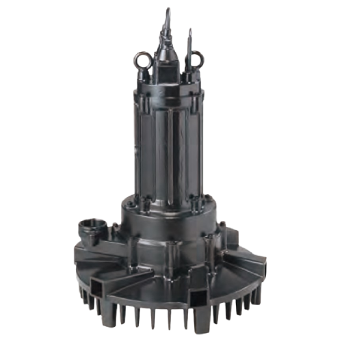
Tsurumi’s submersible aerators are used at water treatment facilities to aerate and agitate industrial wastewater, livestock wastewater and other water that needs treating. More specifically, they provide the primary aeration in reactor tanks and aeration tanks at the heart of the water treatment process, and aeration and agitation in flow regulating tanks. These aerators produce tiny bubbles in the wastewater by furiously mixing in air they draw from above the wastewater’s surface, and discharge the aerated wastewater to the outside. The mixed flow of air and water contains a high amount of dissolved oxygen and makes aeration
SUBMERSIBLE AERATOR TRN SERIES is built to draw air on its own by generating negative pressure behind a patented semi-open impeller with the flow the impeller creates. The air drawn from above the wastewater’s surface is furiously mixed in with the wastewater under the mechanical force of the impeller and guide vanes, to form tiny bubbles. The aerated flow is equally discharged in all directions and the synergistic effect of the airlift and convection that this mechanism causes produces a high amount of dissolved oxygen and enables efficient aeration and agitation and agitation.

Self-Aspirating Design
The specially designed impeller generates negative pressure around it self when rotating. This negative pressure draws in air from above the water surface. As a result, this equipment aerates without the need for a blower. (A blower is required for deep-water aeration.) In addition, no diffuser piping is required; the aerator requires air intake piping only.
High Efficiency Dissolution of Oxygen
The air drawn into the aerator is pressurized by the liquid
impelled by the impeller. Both the liquid and the pressurized air are pushed toward the discharge port by the guide vane. As part of this process, the air and liquid are mixed at a pressure higher than that produced by the depth of the water. This in
Excellent Stirring Performance
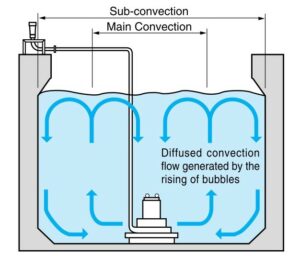
The air contained in the air/liquid mixture discharged from the aerator gives buoyancy to the mixture, and the upward flow of the buoyant liquid generates convection current in the tank. The current stirs the liquid so that it may even out the oxygen
translation throughout the tank.
Outstanding Durability
This aerator incorporates a double mechanical seal, Tsurumi’s field-proven shaft seal mechanism. An Oil Lifter is also provided to extend the service life of the mechanical seal. In addition, this aerator includes Tsurumi’s proprietary air seal mechanism, which significantly extends the service life of the shaft seal mechanism.
• Additional Features
This aerator features the same unique technologies adopted in Tsurumi’s submersible pumps. These include the anti-wicking cable entry, which protects the motor from water intrusion through the cable conductors; motor protection device, which protects motor from overload; and an oil seal that protects the mechanical seal from abrasive particles.
• Main Convection
Convection made by rising
bubbles. (The minimum
distance that must be
provided between each
aerator)
• Sub-convection
The maximum convection
that can keep solids suspended to prevent sedimentation of solids.

| Model | Max.Water Depth m |
Main Convection ɸ m |
Sub-convection | |
|---|---|---|---|---|
| Circular Tank ɸ m |
Square Tank m |
|||
| 32TRN2.75 | 3.5 | 1.4 | 3.5 | 3 |
| 32TRN21.5 | 3.5 | 1.8 | 4.5 | 4 |
| 50TRN42.2 | 3.6 | 2.4 | 6 | 5.5 |
| 50TRN43.7 | 4 | 3 | 7 | 6.5 |
| 50TRN45.5 | 4 | 3.8 | 9 | 8 |
| 80TRN47.5 | 4.5 | 4.4 | 10 | 9 |
| 80TRN412 | 6 | 5.2 | 12 | 11 |
| 80TRN417 | 6 | 5.6 | 13 | 11.5 |
| 100TRN424 | 6 | 6.3 | 14.5 | 13 |
| 150TRN440 | 6 | 7.3 | 17 | 15 |
Silencer & Valve Set……………………………………….1 set
Screwed Flange
(with Packing & Bolts / 17kW and below)…………1 set
JIS 10kg/cm 2 Flange
(with Packing & Bolts / 24kW and above)…………1 set
| Air-inlet Bore mm | 32 | 50 | 80 | 100 | 150 | ||
|---|---|---|---|---|---|---|---|
| Treating Fluid | Type of Fluid | Wastewater and Sewage | |||||
| Fluid Temperature | 0 to 40˚C | ||||||
| Aerator | Structure | Impeller | Semi-open Impeller (special) | ||||
| Shaft Seal | Double Mechanical Seal (with Oil Lifter) | ||||||
| Bearing | Double-shielded Ball Bearing | ||||||
| Materials | Impeller | 410 Stainless Steel Casting | |||||
| Air Passage | Gray Cast Iron | ||||||
| Guide Vane | Gray Cast Iron | ||||||
| Suction Cover | 410 Stainless Steel Casting | ||||||
| Shaft Seal | Silicon Carbide | ||||||
| Motor | Type, Pole | Dry Type Submersible Induction Motor | |||||
| 2, 4-pole | |||||||
| Insulation | Class F | ||||||
| Phase | Three-phase | ||||||
| Starting Method | Direct on Line (7.5kW and below) Star-Delta (12kW and above) |
||||||
| Protection Device (built-in) | Circle Thermal Protector (7.5kW and below) Miniature Thermal Protector (12kW and above) |
||||||
| Lubricant | Turbine Oil (ISO VG32) | ||||||
| Materials | Frame | Gray Cast Iron | |||||
| Shaft | 420 Stainless Steel | ||||||
| Cable | PVC (3.7kW and below) Chloroprene Rubber (5.5kW and above) |
||||||
| No. of Outlets | 6 (17kW and below) 8 (24kW and 40kW) |
||||||
| kW | 200~240V | 380~600V | Material | Length m |
||
|---|---|---|---|---|---|---|
| CoresX mm2 |
Dia. mm |
Cores X mm2 |
Dia. mm |
|||
| 0.75 | 4x1.25 | 11.1 | 4x1.25 | 11.1 | PVC | 6 |
| 1.5 | 4x1.25 | 11.1 | 4x1.25 | 11.1 | PVC | 6 |
| 2.2 | 4x2 | 11.8 | 4x2 | 11.8 | PVC | 6 |
| 3.7 | 4x3.5 | 13.9 | 4x2 | 11.8 | PVC | 6 |
| 5.5 | 4x3.5 | 14.1 | 4x3.5 | 14.1 | Chloroprene Rubber |
8 |
| 7.5 | 4x5.5 | 16.8 | 4x5.5 | 16.8 | Chloroprene Rubber |
8 |
| 12 | 4x3.5 3x3.5 2x1.25 |
14.1 12.9 9.8 |
4x3.5 3x3.5 2x1.25 |
14.1 12.9 9.8 |
Chloroprene Rubber | 8 |
| 17 | 4x5.5 3x5.5 2x1.25 |
16.8 15.2 9.8 |
4x5.5 3x5.5 2x1.25 |
16.8 15.2 9.8 |
Chloroprene Rubber | 8 |
| 24 | 4x14 3x14 2x1.25 |
21.7 19.7 9.8 |
4x14 3x14 2x1.25 |
21.7 19.7 9.8 |
Chloroprene Rubber | 10 |
| 40 | 4x22 3x22 2x1.25 |
28.8 26.1 9.8 |
4x14 3x14 2x1.25 |
21.7 19.7 9.8 |
Chloroprene Rubber | 10 |
| Air-inlet Bore mm |
Model | Motor Output kW |
Speed(S.S.) min-1 |
Starting Method |
Max.Water Depth m |
Air Flow Rate *- Max.Water Depth m3/h |
No. of Outlets | Solids Passage mm |
Dry Weight ** kg |
|---|---|---|---|---|---|---|---|---|---|
| 32 | 32TRN2.75 | 0.75 | 3000/3600 | D.O.L. | 3.5 | 7/8 | 6 | 10 | 55 |
| 32TRN21.5 | 1.5 | 3000/3600 | D.O.L. | 3.5 | 20/17 | 6 | 12 | 55 | |
| 50 | 50TRN42.2 | 2.2 | 1500/1800 | D.O.L. | 3.6 | 39/38 | 6 | 12 | 140 |
| 50TRN43.7 | 3.7 | 1500/1800 | D.O.L. | 4 | 55/60 | 6 | 12 | 150 | |
| 50TRN45.5 | 5.5 | 1500/1800 | D.O.L. | 4 | 78/79 | 6 | 15 | 170 | |
| 80 | 80TRN47.5 | 7.5 | 1500/1800 | D.O.L. | 4.5 | 124/112 | 6 | 15 | 190 |
| 80TRN412 | 12 | 1500/1800 | Star-Delta | 6.0 | 157/155 | 6 | 15 | 200 | |
| 80TRN417 | 17 | 1500/1800 | Star-Delta | 6.0 | 202/220 | 6 | 15 | 220 | |
| 100 | 100TRN424 | 24 | 1500/1800 | Star-Delta | 6.0 | 388/342 | 8 | 22 | 435 |
| 150 | 150TRN440 | 40 | 1500/1800 | Star-Delta | 6.0 | 528/506 | 8 | 25 | 583 |
The air flow rates are expressed at the standard condition, i.e. temperature of 20°C, 1 atm and may vary by up to approximately 5%
Unit: mm
| MODEL | A | B | C | D | E |
|---|---|---|---|---|---|
| 32TRN2.75 | 32 | 400 | 473 | 81 | 371 |
| 32TRN21.5 | 32 | 400 | 473 | 81 | 371 |
| 50TRN42.2 | 50 | 700 | 689 | 123 | 660 |
| 50TRN43.7 | 50 | 700 | 694 | 123 | 660 |
| 50TRN45.5 | 50 | 700 | 835 | 123 | 660 |
| 80TRN47.5 | 80 | 700 | 868 | 133 | 660 |
| 80TRN412 | 80 | 700 | 898 | 133 | 660 |
| 80TRN417 | 80 | 700 | 958 | 133 | 660 |
| 100TRN424 | 100 | 1000 | 1254 | 272 | 980 |
| 150TRN440 | 150 | 1000 | 1459 | 269 | 980 |