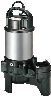
The PU series is a type of vortex pump that has been specifically created to manage a range of different fluids, including raw sewage, wastewater, and other liquids that are commonly found in industrial and commercial applications. This pump has been designed with a solid handling system that ensures it can operate efficiently without getting clogged up, even when handling sewage.
The pump is made from a combination of special resin and stainless steel, which makes it lightweight and resistant to corrosion. This means that it can be used in a variety of different environments and applications, without suffering from any significant wear and tear. Overall, the PU series vortex pump is a reliable and effective choice for anyone looking for a pump that can handle challenging fluid management tasks.
| Category | Series | Discharge Bore mm | Impeller | Model | Motor Output kW | ||||||
|---|---|---|---|---|---|---|---|---|---|---|---|
| 0.15 | 0.25 | 0.4 | 0.75 | 1.5 | 2.2 | 3.7 | |||||
| Sewage | PU | 40 - 80 | Vortex | Standard | ● | ● | ● | ● | ● | ● | ● |
| Automatic | ● | ● | ● | ● | ● | ● | ● | ||||
| Auto-alternation | ● | ● | ● | ● | ● | ● | ● | ||||
| Wastewater | PN | 40 - 80 | Vortex | Standard | ● | ● | ● | ● | ● | ● | |
| Automatic | ● | ● | ● | ● | ● | ● | |||||
| Auto-alternation | ● | ● | ● | ● | ● | ● | |||||
| Wastewater
-High Head- |
PSF | 40 - 65 | Closed | Standard | ● | ● | ● | ● | ● | ● | |
| Automatic | ● | ● | ● | ● | ● | ● | |||||
| Auto-alternation | ● | ● | ● | ● | ● | ● | |||||
| Wastewater -Horizontal- |
PLS | 50 | Vortex | Standard | ● | ● | ● | ||||
| Seawater | TM | 40 - 80 | Vortex | Standard | ● | ● | ● | ● | ● | ● | |
| Automatic | ● | ● | ● | ● | ● | ● | |||||
| Wastewater -Economic- |
OM | 32 | Vortex | Standard | ● | ||||||
| Automatic | ● | ||||||||||
• Draining sewage from factory, residence, hotel, restaurant, etc.
• Pumping rainwater and springwater at a place where foreign objects are likely to run into the water
• Transferring wastewater between the tanks at small-scale treatment facility
• Circulating water in waterscape garden (e.g. waterfall, fountain, koi pond, etc.)
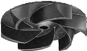
The vortex impeller is Rotation of the impeller produces a whirling, centrifugal action between the impeller and the pump casing, and it moves the fluid through the pump. Being coupled with a wide pump casing, wastewater containing solid matters can be pumped out without obstruction.
TOK Application Table
| Model | Applicable Motor Output |
|---|---|
| TOK4-P | 0.15 to 0.75kW |
| TOK2-65 | 1.5kW |
| TOK2-65T | 2.2 to 3.7kW |
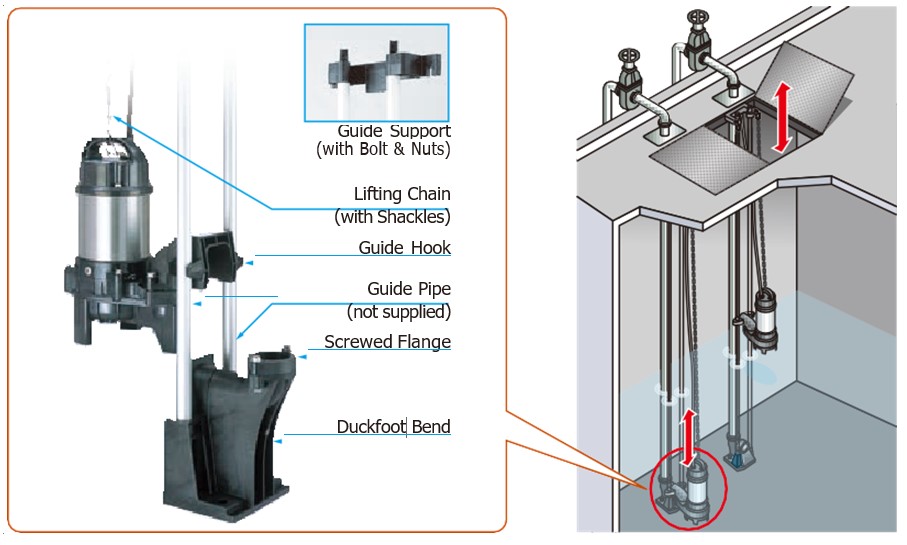
Accessories
• Duckfoot Bend
• Guide Hook
• Guide Support with Bolts & Nuts
• Lifting Chain with Shackles (4m for TOK4-P, 5m for TOK2-65 / 65T)
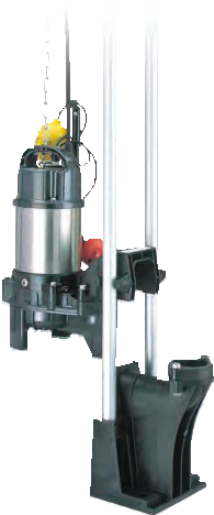
The TOK guide rail fitting system connects the
pump to and from the piping easily just by lowering
and hoisting the pump, allowing easy maintenance
and inspection without the need to enter the sump.
Made of high-quality resin, the TOK is designed
for lightweight, small to middle sized pumps.
Rubber bellows attached to the guide hook are
inverted to the duckfoot bend when the pump
starts operating, and it seals by the pumping
pressure. This eliminates leakage at the seal
even if a lightweight pump is used in combination
with the TOK.
The TOK is available in all motor output ranges of
the PU, PN, and PSF series.
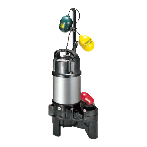
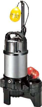
The float type automatic model has an integral control circuit and two float switches that operate at a low voltage. It operates automatically in response to the change in water levels.
This model can be identified by the suffix “A” and is availa-ble in all motor output ranges of the PU, PN, PSF, and TM series.
The cylindrical float type automatic model is available only for the OM-series. Adoption of the unique float switch has made even the automatic model very compact and enables it to be installed in a limited space. Automatic operation is possible with a simple power panel.


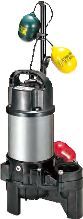
The auto-alternation model is used along with an automatic model. The combinational use of these two pumps enables each pump to operate alter- nately without control panel.
The auto-alternation model has three floats and can be identified by the suffix “W”. Refer to model selection for availability and model num- bers of the PU, PN, and PSF series.

| Discharge Bore mm | 40 | 50 | 80 | ||
|---|---|---|---|---|---|
| Pumping Fluid | Type of Fluid | Sewage, Wastewater, and Water carrying Solid Matters |
|||
| Fluid Temperature | 0 to 40℃ | ||||
| Pump | Structure | Impeller | Vortex | ||
| Shaft Seal | Double Mechanical Seal (with Oil Lifter) | ||||
| Bearing | Double-shielded Ball Bearing | ||||
| Materials | Impeller | Glass-fiber Reinforced Resin | |||
| Casing | Glass-fiber Reinforced Resin | ||||
| Shaft seal | Silicon Carbide | ||||
| Motor | Type, Pole | Dry-type Submersible Induction Motor, 2-pole |
|||
| Insulation | Class E | ||||
| Phase | Single-phase (suffix "S") Three-phase |
||||
| Starting Method | Capacitor Run (single-phase only) Direct on Line |
||||
| Circle Thermal Protector Miniature Thermal Protector (40PU2.15S, 40PU2.25S & 50PU2.4S only) |
|||||
| Protection Device (Built-in) | |||||
| Lubricant | Liquid Paraffin (ISO VG32) | ||||
| Materials | Frame | 304 Stainless Steel | |||
| Shaft | 420 Stainless Steel (0.15kW only) 304 Stainless Steel |
||||
| Cable | PVC | ||||
| Discharge Connection | Screwed Flange | ||||
| Model | 100-120V | 200-240V | Length
m |
Material | ||
|---|---|---|---|---|---|---|
| Cores × mm2 |
Outer Dia. mm |
Cores × mm2 |
Outer Dia . mm |
|||
| 40PU2.15S | 3 × 1.25 | 10.1 | 3 × 1.25 | 10.1 | 5 | PVC |
| 40PU2.25S | 3 × 1.25 | 10.1 | 3 × 1.25 | 10.1 | ||
| 50PU2.4S | 3 × 1.25 | 10.1 | 3 × 1.25 | 10.1 | ||
| 50PU2.75S | 3 × 2.0 | 10.9 | 3 × 1.25 | 10.1 | ||
| Model | 200-240V | 380-600V | Length m |
Material | ||
|---|---|---|---|---|---|---|
| Cores × mm2 |
Outer Dia. mm |
Cores × mm2 |
Outer Dia. mm |
|||
| 40PU2.15 | 4 × 1.25 | 11.1 | 4 × 1.25 | 11.1 | 6 | PVC |
| 40PU2.25 | 4 × 1.25 | 11.1 | 4 × 1.25 | 11.1 | ||
| 50PU2.4 | 4 × 1.25 | 11.1 | 4 × 1.25 | 11.1 | ||
| 50PU2.75 | 4 × 1.25 | 11.1 | 4 × 1.25 | 11.1 | ||
| 80PU21.5 | 4 × 1.25 | 11.1 | 4 × 1.25 | 11.1 | ||
| 80PU22.2 | 4 × 2.0 | 11.8 | 4 × 1.25 | 11.1 | ||
| 80PU23.7 | 4 × 3.5 | 13.9 | 4 × 2.0 | 11.8 | ||
| Discharge Bore mm |
Model | Motor Output kW |
Phase | Starting Method |
Solids Passage mm |
Dry Weight kg | |||
|---|---|---|---|---|---|---|---|---|---|
| Standard | Automatic | Auto-alternation | Standard | Auto & Auto-alternation |
|||||
| 40 | 40PU2.15S | 40PUA2.15S | 40PUW2.15S | 0.15 | Single | Capacitor Run | 35 | 6.1 | 6.7 |
| 40 | 40PU2.15 | 40PUA2.15 | 40PUW2.15 | 0.15 | Three | D.O.L. | 35 | 5.6 | 6.3 |
| 40 | 40PU2.25S | 40PUA2.25S | 40PUW2.25S | 0.25 | Single | Capacitor Run | 35 | 7.1 | 7.8 |
| 40 | 40PU2.25 | 40PUA2.25 | 40PUW2.25 | 0.25 | Three | D.O.L. | 35 | 6.1 | 6.8 |
| 50 | 50PU2.4S | 50PUA2.4S | 50PUW2.4S | 0.4 | Single | Capacitor Run | 35 | 7.1 | 7.8 |
| 50 | 50PU2.4 | 50PUA2.4 | 50PUW2.4 | 0.4 | Three | D.O.L. | 35 | 7 | 7.7 |
| 50 | 50PU2.75S | 50PUA2.75S | - | 0.75 | Single | Capacitor Run | 35 | 8.9 | 9.5 |
| 50 | 50PU2.75 | 50PUA2.75 | 50PUW2.75 | 0.75 | Three | D.O.L. | 35 | 8.3 | 9 |
| 80 | 80PU21.5 | 80PUA21.5 | 80PUW21.5 | 1.5 | Three | D.O.L. | 46 | 16 | 16.9 |
| 80 | 80PU22.2 | 80PUA22.2 | 80PUW22.2 | 2.2 | Three | D.O.L. | 46 | 22 | 23 |
| 80 | 80PU23.7 | 80PUA23.7 | 80PUW23.7 | 3.7 | Three | D.O.L. | 46 | 27 | 28 |
| Model | d | A | B | H | W1 | W2 |
|---|---|---|---|---|---|---|
| 40PU2.15S | 40 | 225 | 154 | 377 | 340 | 105 |
| 40PU2.15 | 40 | 225 | 154 | 377 | 340 | 105 |
| 40PU2.25S | 40 | 236 | 162 | 360 | 325 | 110 |
| 40PU2.25 | 40 | 236 | 162 | 349 | 310 | 110 |
| 50PU2.4S | 50 | 236 | 162 | 360 | 325 | 110 |
| 50PU2.4 | 50 | 236 | 162 | 360 | 325 | 110 |
| 50PU2.75S | 50 | 236 | 162 | 380 | 345 | 110 |
| 50PU2.75 | 50 | 236 | 162 | 374 | 335 | 110 |
| 80PU21.5 | 80 | 295 | 196 | 475 | 430 | 150 |
| 80PU22.2 | 80 | 311 | 212 | 583 | 520 | 155 |
| 80PU23.7 | 80 | 311 | 212 | 618 | 555 | 155 |
