Search

Floating Decanters FHP Series


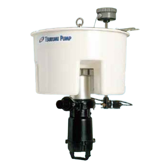
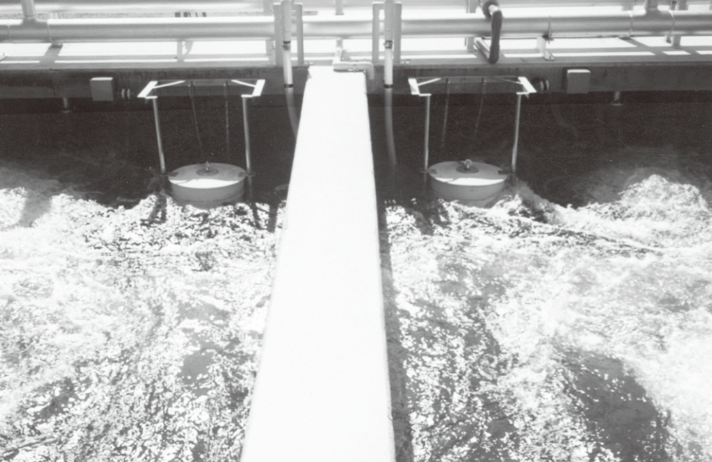
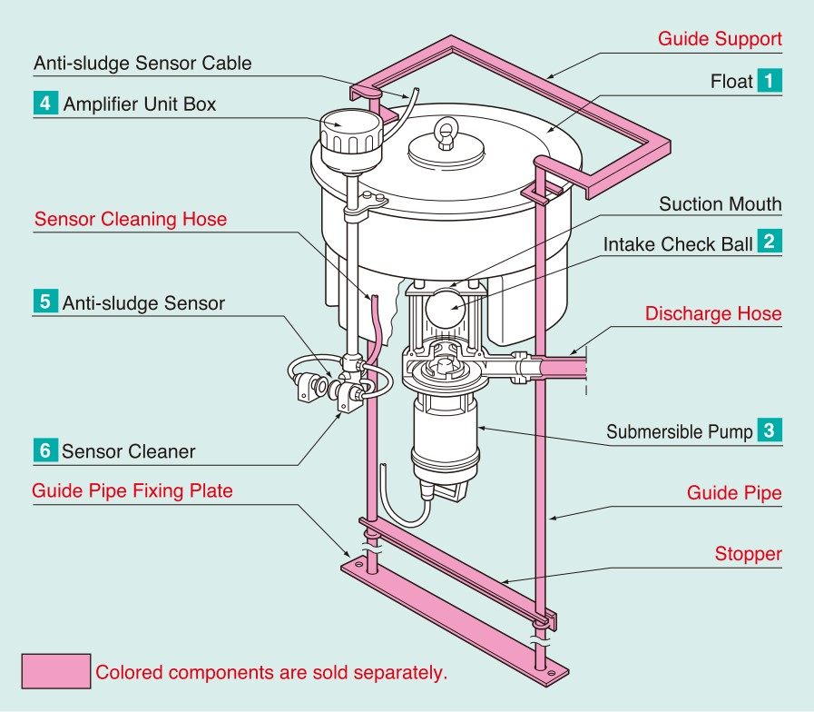
FLOATING DECANTERS FHP SERIES is a floating decanter designed for discharging supernatant liquid in SBR. It consists of a submersible pump, sludge sensor, and a float.

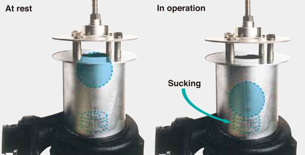
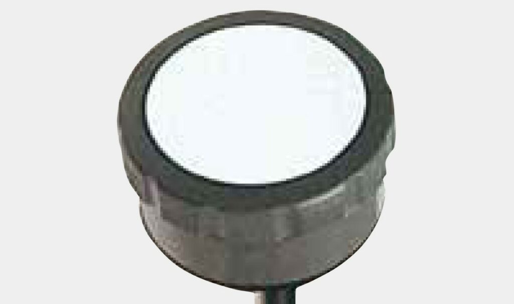
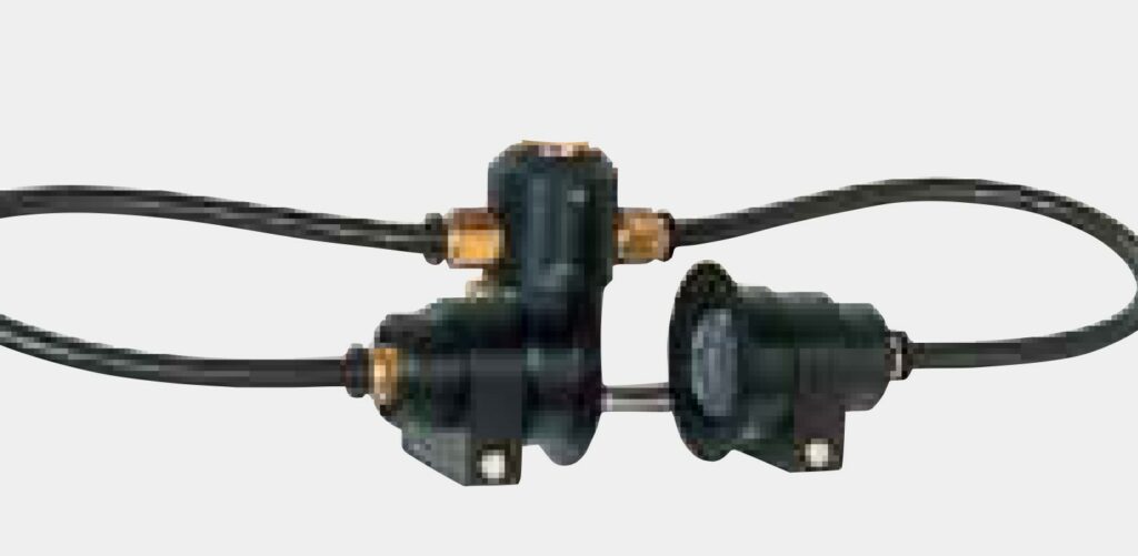
The sludge sensor is a monitoring device that prevents unexpected inflow of sludge or other sediment and helps the pump solely discharge supernatant liquid. When the pump is not in operation, a check ball incorporated in the intake closes the suction opening by buoyancy, thus preventing the inflow of floating sludge into the suction casing.

FLOATING DECANTERS FHP SERIES

Photosensor prevents sludge inflow, helps discharge only supernatant liquid. Ideal for use under unstable water levels.

Floating Decanters Photo FHP

Features

  • The sludge surface monitoring device prevents unexpected inflow of sludge and helps the pump solely discharge supernatant liquid.
  • A float makes the pump particularly useful for the application where the water level fluctuates widely.
  • An incorporated control circuit automatically stops operation upon receiving warning signals from the photosensor which would detect a water level drop to near the sludge interface layer.
  • The sensor surfaces are automatically washed with pressurized water to be kept clean for perfect monitoring.

Applications

  • Discharging supernatant liquid in SBR
  • Discharging supernatant liquid at a facility where such process is required

Model Selection 50/60Hz

Discharge Bore
mm
Model Motor Output
kW
Phase Speed (S.S.)
min-1
Starting Method Dry Weight
*kg
Cable Length
m
40 FHP3-3 0.25 Single 3000/3600 Capacitor Start 29 6
40 FHP3-3T 0.25 Three 3000/3600 D.O.L. 27 6
50 FHP2-4 0.4 Single 3000/3600 Capacitor Start 29 6
50 FHP2-4T 0.4 Three 3000/3600 D.O.L. 27 6
50 FHP4-8T 0.75 Three 3000/3600 D.O.L. 28 6
80 FHP2-15T 1.5 Three 3000/3600 D.O.L. 60 6

Major Components & Specifications

Major Components & Specifications
Discharge Bore mm 40 50 80
Pumping Fluid Type of Fluid Treated Water
Fluid Temperature 0 to 40˚C
Pump Structure Impeller Channel
Shaft Seal Double Mechanical Seal
Bearing Double-shielded Ball Bearing
Materials Impeller Gray Cast Iron
Casing Gray Cast Iron
Shaft seal Silicon Carbide
Float FRP
Motor Type, Pole Dry Type Submersible Induction Motor, 2-pole
Insulation Class E
Class F (1.5kW only)
Phase Single-phase
Three-phase (suffix "T")
Starting Method Capacitor Start (Single-phase only) Direct on Line
Protection Device (built-in) Circle Thermal Protector
Lubricant Turbine Oil (ISO VG32)
Materials Frame Gray Cast Iron
Shaft 420 Stainless Steel
Cable PVC
Discharge Connection Hose Coupling

Performance Curves

Dimensions

Standard Accessories

  • Hose Coupling
  • Anti-sludge Sensor Cable 6m
  • Lifting Chain 3m* (with Shackles)
    *5m for 1.5kW
Standard Accessories photo

Structural Features

1.Float
The float sustains a submersible pump by buoyancy at an appropriate position.
Made of fiber reinforced plastic (FRP), the float is filled with polystyrene foam which prevents the loss of buoyancy in case the float is broken.

2.Intake Check Ball
A check ball incorporated in the intake closes the suction mouth by buoyancy when the pump stops operating thus preventing the inflow of floating sludge.
During operation, the ball is sucked in by the pump’s suction power to take in supernatant liquid.

3.Pumping Section
Each component, such as dual inside mechanical seal, motor protector, and anti-wicking cable entry, represents Tsurumi’s outstanding expertise.

4.Amplifier Unit Box

Amplifier Unit Box FHP

5.Anti-sludge Sensor
When the amount of light transmitted from an emitter via glass fibers is reduced by a certain density of sludge existing in the liquid, the sensor identifies the light amount and sends corresponding signals to the control panel to stop or operate the pump not to suck up sludge.

Anti-sludge Sensor FHP

6.Sensor Cleaner
The sensor cleaner spouts a jet of clean water from its nozzle to wash the light emitter and receiver at fixed intervals. The pressurized water can be treated water coming from a submersible pump installed in the spray pump tank.

Recommendation;

  • The washing shall be performed for 5 minutes every 1.5 hours during the aeration process.
  • The amount of washing water shall be regulated with a valve over a range of 10 to 20 L/min and the pressure, 0.5 to 1 kg/cm2.