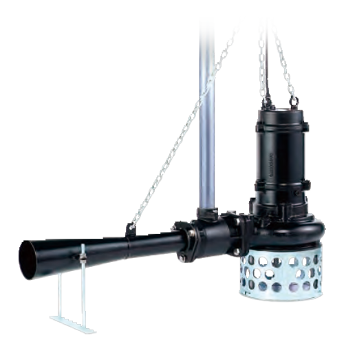
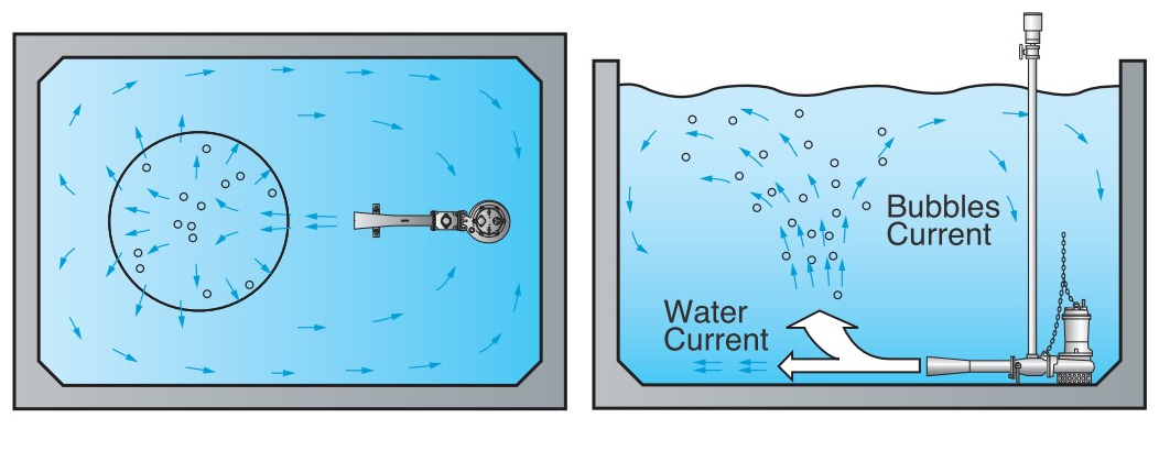
SUBMERSIBLE SELF-ASPIRATING JET AERATORS BER SERISE is a combination of a customized B-series pump and a venturi-jet based diffuser. They draw in air from above water’s surface by generating negative pressure around the nozzle with the flow from the pump. The air is mixed into the wastewater by this jet injector mechanism and sprayed underwater by the diffuser, to aerate and agitate the wastewater at the same time. In the process, tiny bubbles form inside the diffuser and increase the amount of dissolved oxygen in the wastewater. The mixed air-water is ejected powerfully in one direction, which effectively agitates the water across a wide area.
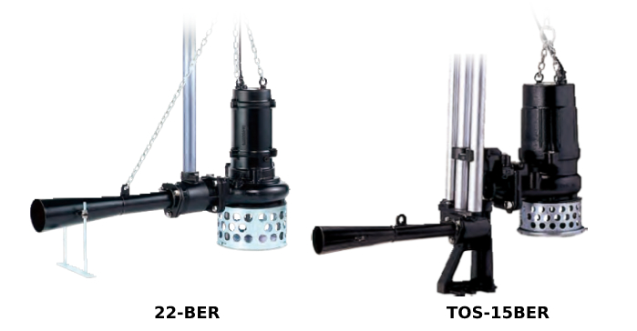
SUBMERSIBLE SELF-ASPIRATING JET AERATORS BER SERISE is available not only as a free-standing model but also as a guide rail model, so that maintenance and inspection can be performed without entering the sump.
FEATURES
APPLICATIONS
| Model | Air-inlet Bore mm |
Motor Output kW |
Phase | Starting Method |
Solids Passage mm |
Max. Water Depth *2 50 / 60Hz m |
Dimensions L x H mm |
Dry Weight*3 kg |
Cable Length m |
|||
|---|---|---|---|---|---|---|---|---|---|---|---|---|
| Free Standing |
Guide Rail Fitting |
Free Standing | Guide Rail Fitting | Free Standing | Guide Rail Fitting | |||||||
| 8-BER | TOS-8BER | 25 | 0.75 | Three | D. O. L. | 20 | 4 / 3.5 | 674 x 464 | 674 x 514 | 28 | 23 | 6 |
| 15-BER | TOS-15BER | 32 | 1.5 | Three | D. O. L. | 20 | 4 | 895 x 562 | 910 x 603 | 43 | 34 | 6 |
| 22-BER | TOS-22BER | 50 | 2.2 | Three | D. O. L. | 35 | 4.5 | 1158 x 705 | 1162 x 793 | 75 | 73 | 6 |
| 37-BER | TOS-37BER | 50 | 3.7 | Three | D. O. L. | 35 | 5 | 1163 x 779 | 1167 x 862 | 91 | 87 | 6 |
| 55-BER | TOS-55BER | 50 | 5.5 | Three | D. O. L. | 35 | 6 | 1415 x 942 | 1422 x 1006 | 142 | 126 | 8 |
| Model | Motor Output kW |
Max.Water Depth 50/60Hz m |
Max. Tank Dimensions 50/60Hz | ||
|---|---|---|---|---|---|
| Length m |
Width m |
Depth m |
|||
| 8-BER | 0.75 | 4 / 3.5 | 3 | 2 | 4 / 3.5 |
| 15-BER | 1.5 | 4 | 4 | 3.5 | 4 |
| 22-BER | 2.2 | 4.5 | 5 | 4.5 | 4.5 |
| 37-BER | 3.7 | 5 | 6 | 5 | 5 |
| 55-BER | 5.5 | 6 | 7 | 7 | 6 |
| BER | ||||||
|---|---|---|---|---|---|---|
| 8-BER | 15-BER | 22-BER | 37-BER | 55-BER | ||
| PUMP | Air-inlet Bore mm | 25 | 32 | 50 | ||
| Air-inlet Connection | Threaded Oval Flange | |||||
| Diffuser | Structure Steel + Nylon Coated | |||||
| Solids Passage mm | 20 | 35 | ||||
| Impeller | Channel | |||||
| Gray Cast Iron | ||||||
| Suction Cover | Gray Cast Iron | |||||
| Middle Plate | - | |||||
| Oil Seal | Nitrile Butadiene Rubber | |||||
| Air Passage & Guide Vane / Casing |
Gray Cast Iron | |||||
| Dual Inside Mechanical Seals (with Oil Lifter) | ||||||
| Shaft Seal | Silicon Carbide | |||||
| MOTOR | Type | Continuous-dutyRated, Dry-type Induction Motor | ||||
| Output kW | 0.75 | 1.5 | 2.2 | 3.7 | 5.5 | |
| Phase | Three | |||||
| Pole | 2 | 4 | ||||
| Speed (S.S.) 50/60Hz min-1 |
3000/3600 | 1500/1800 | ||||
| Insulation | E | F | ||||
| Starting Method | D.O.L. | |||||
| Motor Protector (built-in) |
- | |||||
| CTP | ||||||
ml Lubricant |
440 | 900 | 1350 | 4300 | ||
| Turbine Oil (ISO VG32) | ||||||
| Frame | Gray Cast Iron | |||||
| Shaft | 420 Stainless Steel | |||||
m Power Cable |
6 | 8 | ||||
| PVC | Chloroprene Rubber |
|||||
| Max. Water Depth *1 50/60Hz m |
4.0 / 3.5 | 4 | 4.5 | 5 | 6 | |
| No. of Outlets m | 1 (One Direction) | |||||
| Dry Weight *2 | Free Standing kg | 28 | 43 | 75 | 91 | 142 |
| Guide Rail Fitting kg | 23 | 34 | 73 | 87 | 126 | |
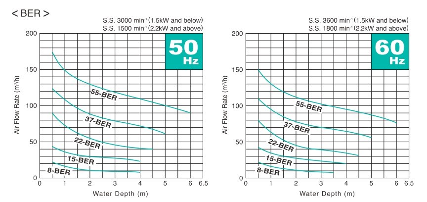
AIR FLOW RATE – WATER DEPTH CURVES
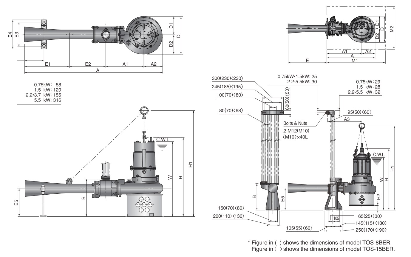
FREE STANDING
Unit: mm
| Model | A | A1 | A2 | B | D | D1 | D2 | W | H | H1 | E1 | E2 | E3 | E4 | E5 |
|---|---|---|---|---|---|---|---|---|---|---|---|---|---|---|---|
| 8-BER | 674 | 200 | 97 | 195 | 194 | 97 | 97 | 435 | 464 | 595 | 208 | 169 | 150 | 180 | 150 |
| 15-BER | 895 | 244 | 114 | 225 | 222 | 111 | 111 | 490 | 562 | - | 270 | 267 | 150 | 180 | 159 |
| 22-BER | 1158 | 317 | 154 | 312 | 316 | 150 | 166 | 640 | 679 | 1094 | 380 | 307 | 220 | 260 | 232 |
| 37-BER | 1163 | 317 | 159 | 317 | 325 | 150 | 175 | 710 | 753 | 1145 | 380 | 307 | 220 | 260 | 237 |
| 55-BER | 1415 | 360 | 194 | 341 | 391 | 188 | 203 | 820 | 942 | 1169 | 460 | 401 | 220 | 260 | 256 |
GUIDE RAIL FITTING
Unit: mm
| Model | A | A1 | A2 | A3 | B | D | D1 | D2 | W | H | H1 | H2 | M1 | M2 | E | E5 |
|---|---|---|---|---|---|---|---|---|---|---|---|---|---|---|---|---|
| TOS-8BER | 385 | 288 | 97 | 238 | 238 | 194 | 97 | 97 | 485 | 514 | 645 | 50 | 550 | 350 | 289 | 200 |
| TOS-15BER | 467 | 353 | 114 | 293 | 250 | 222 | 111 | 111 | 530 | 603 | - | 41 | 650 | 450 | 443 | 200 |
| TOS-22BER | 616 | 462 | 154 | 367 | 385 | 316 | 150 | 166 | 730 | 767 | 973 | 88 | 700 | 450 | 546 | 320 |
| TOS-37BER | 621 | 462 | 159 | 367 | 385 | 325 | 150 | 175 | 795 | 836 | 1048 | 83 | 700 | 450 | 546 | 320 |
| TOS-55BER | 711 | 517 | 194 | 422 | 385 | 391 | 188 | 203 | 885 | 1006 | 1368 | 65 | 750 | 500 | 711 | 320 |
SILENCER & VALVE SET
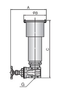
Unit: mm
| Pipe Bore | A | B | C | G |
|---|---|---|---|---|
| ɸ 25 | 147 | 91 | 150 | Rc 1 |
| ɸ 32 | 180 | 116 | 208 | Rc 1- ⅟₄ |
| ɸ 50 | 230 | 154 | 285 | Rc 2 |
Material of Silencer : PVC
SUBMERSIBLE AERATOR TRN SERIES & SUBMERSIBLE SELF-ASPIRATING JET AERATORS BER SERISE
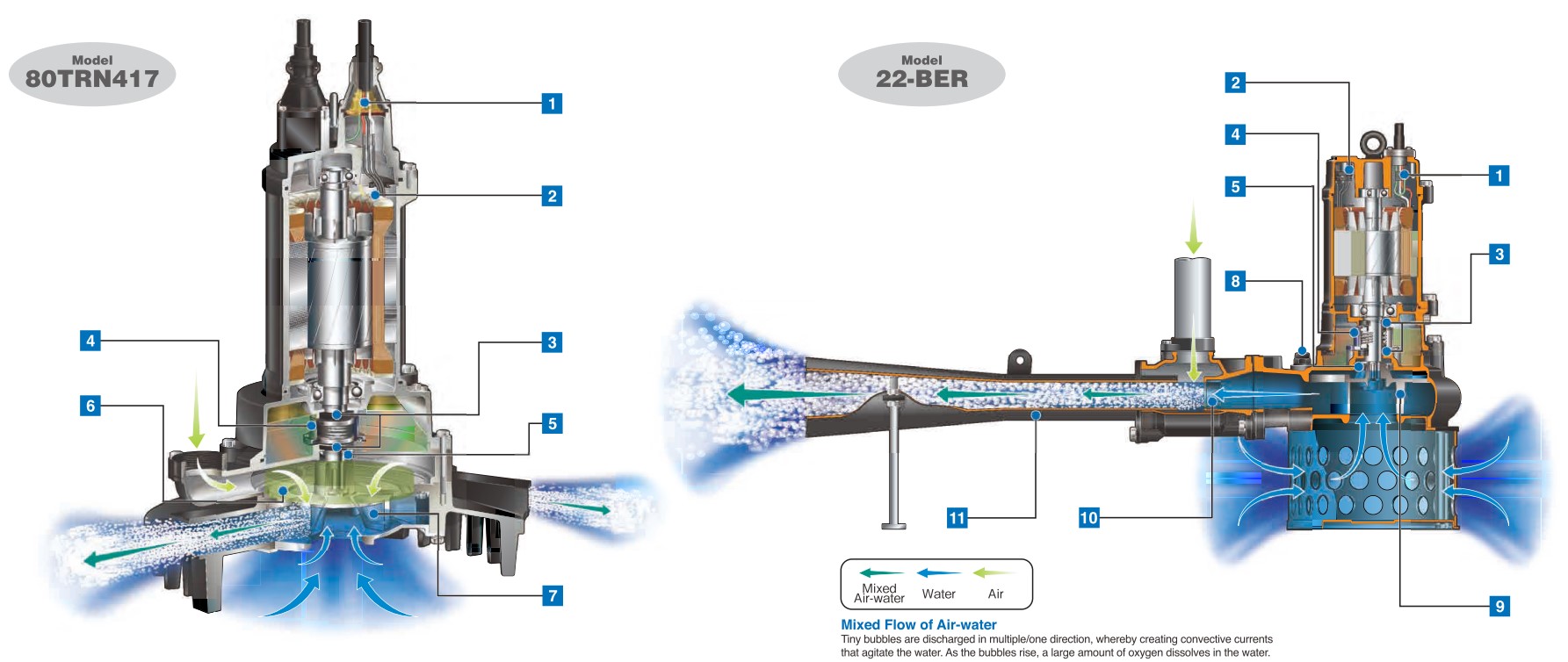
1.Anti-wicking Cable Entry
Prevents water incursion due to capillary action should the cable sheath be damaged or the end of cable submerged. Also prevents moist air from infiltrating the motor housing and condensation from forming inside the housing due to temperature differences between the housing and outside air.
2.Motor Protector
Single-phase:
Detects excess heat, therefore, protecting the pump against overheating and dry-running.
Three-phase:
React to excessive heat caused by dry-running. The bimetal strip opens to cause the control panel to shut the power supply.
Circle Thermal Protector
Directly cuts the motor circuit if excessive heat builds up or overcurrent occurs in the motor.
3.Dual Inside Mechanical Seals with Silicon Carbide Face
Isolated in the oil chamber where a clean, non-corrosive and abrasion-free lubricating environment is maintained. Compared with the water-cooled outside mechanical seal, it reduces the risk of failure caused by dry-heating and adhering matter. The Silicon carbide provides 5 times higher corrosion, wear and heat resistance than the tungsten carbide. Rubber parts are made of NBR or FPM (FKM) which provides higher resistance to heat and chemicals.
4.Oil Lifter
Provides lubrication and cooling of the seal faces down to 1/3 of normal oil level, thus maintaining a stable shaft sealing effect and prolonging seal life longer. The Oil Lifter is Tsurumi original design.
5.Oil Seal
Used as a “Dust Seal,” it protects the mechanical seal from abrasive particles.
6.Air Seal Mechanism (TRN)
Protects the mechanical seals by flooding the air passage with an “air seal” that prevents water from contacting the mechanical seals during operation. This proprietary technology helps to prolong the service-life of the mechanical seals.
7.Patented Semi-open Impeller & Suction Cover (TRN)
Generates a liquid flow that causes negative pressure to form on the backside of the impeller vanes and draw in air from above the water’s surface. Both the impeller and suction cover are highly wear-resistant 410 stainless steel casting.
8.Air Release Valve (BER)
Fitted on the pump casing to prevent the air lock. When air flows through the valve, the ball stays at the bottom, but when the pumped water starts to flow, the ball closes the outlet because of its buoyancy.
9.Semi-open Channel Impeller (BER)
Minimizes the possibility of trouble due to clogging by foreign matters.
10.Nozzle Ring (BER)
Channels the water discharged from the pump into a jet, as part of the jet injector mechanism.
11.Diffuser (BER)
Creates a mixed flow of air and water by injecting the aspirated air into the water.
• Main Convection
Convection made by rising
bubbles. (The minimum
distance that must be
provided between each
aerator)
• Sub-convection
The maximum convection
that can keep solids sus-
pended to prevent sedi-
mentation of solids.